Sunday, February 19, 2012


Basic PLC - Programming
Programming PLC
The ladder diagram has and continues to be the traditional way of representing electrical sequences of operations. These diagrams represent the interconnection of field devices in such a way that the activation, or turning ON, of one device will turn ON another device according to a predetermined sequence of events.

The original ladder diagrams were established to represent hardwired logic circuits used to control machines or equipment. Due to wide industry use, they became a standard way of communicating control information from the designers to the users of equipment. As programmable controllers were introduced, this type of circuit representation was also desirable because it was easy to use and interpret and was widely accepted in industry.
Programmable controllers can implement all of the “old” ladder diagram conditions and much more. Their purpose is to perform these control operations in a more reliable manner at a lower cost. A PLC implements, in its CPU, all of the old hardwired interconnections using its software instructions. This is accomplished using familiar ladder diagrams in a manner that is transparent to the engineer or programmer.
Contacts Symbols in PLCs
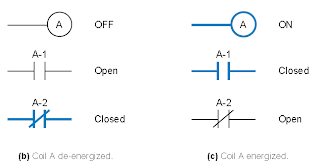
Programmable controller contacts and electro mechanical relay contacts operate in a very similar fashion. For example , let us take relay which has two sets of contacts, one normally open contact and one normally closed contact. If relay coil A is not energized (i.e it is OFF), contact A-1 will remain open and and contact A-2 will remain closed. Conversely if coil A is energized or turned ON, contact A-1 will close and contact A-2 will open.

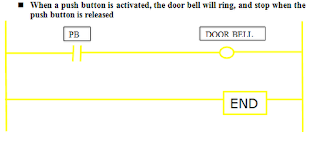
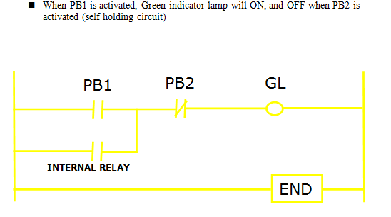
Example 1 :
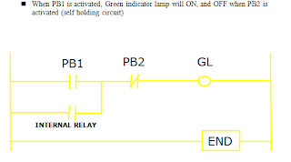
Example 2 :
The ladder diagram has and continues to be the traditional way of representing electrical sequences of operations. These diagrams represent the interconnection of field devices in such a way that the activation, or turning ON, of one device will turn ON another device according to a predetermined sequence of events.

The original ladder diagrams were established to represent hardwired logic circuits used to control machines or equipment. Due to wide industry use, they became a standard way of communicating control information from the designers to the users of equipment. As programmable controllers were introduced, this type of circuit representation was also desirable because it was easy to use and interpret and was widely accepted in industry.
Programmable controllers can implement all of the “old” ladder diagram conditions and much more. Their purpose is to perform these control operations in a more reliable manner at a lower cost. A PLC implements, in its CPU, all of the old hardwired interconnections using its software instructions. This is accomplished using familiar ladder diagrams in a manner that is transparent to the engineer or programmer.
Contacts Symbols in PLCs
Programmable controller contacts and electro mechanical relay contacts operate in a very similar fashion. For example , let us take relay which has two sets of contacts, one normally open contact and one normally closed contact. If relay coil A is not energized (i.e it is OFF), contact A-1 will remain open and and contact A-2 will remain closed. Conversely if coil A is energized or turned ON, contact A-1 will close and contact A-2 will open.


Example 1 :

Example 2 :
Wednesday, February 08, 2012
Basic PLC - PLC Programming (Ladder Diagram)
Creating Flow Chart
Flowcharts are helpful in understanding a complicated process. This is especially true if you have to make decisions and do different steps depending on those decisions. By looking at a flowchart you can visually follow different paths through the chart. For each step on a flowchart you can ask yourself "Is this step necessary? Can it be improved?" . Flowcharts are very essential for you to complete your ladder diagram. Without a flowchart you will face difficulties in order to complete your ladder diagram.
You can make your flowcharts easier to understand and less subject to errors by using only a fixed set of structures. These structures include:
Sequence
The reader would start at the Start shape and follow the arrows from one rectangle to the other, finishing at the End shape. A sequence is the simplest flowcharting construction. You do each step in order.
If your charts are all sequences, then you probably don't need to draw a flowchart. You can type a simple list using your word processor. The power of a flowchart becomes evident when you include decisions and loops.
Decision
Another structure is called a decision, "If Then.. Else" or a conditional. A question is asked in the decision shape. Depending on the answer the control follows either of two paths. Example, if the temperature is going to be less than freezing (32 degrees Fahrenheit) the tomatoes should be covered.
Loop
This structure allows you to repeat a task over and over. It is not important that you remember whether the loop is a "Do While" or "Repeat Until" loop, only that you can check the condition at the start of the loop or at the end. You can also have the conditions reversed and your loop is still a structured design loop.
Ladder Diagram
Ladder logic is the main programming method used for PLCs. As mentioned before, ladder logic has been developed to mimic relay logic. The decision to use the relay logic diagrams was a strategic one. By selecting ladder logic as the main programming method, the amount of retraining needed for engineers and tradespeople was greatly reduced.
Modern control systems still include relays, but these are rarely used for logic. A relay is a simple device that uses a magnetic field to control a switch. When a voltage is applied to the input coil, the resulting current creates a magnetic field. The magnetic field pulls a metal switch (or reed) towards it and the contacts touch, closing the switch. The contact that closes when the coil is energized is called normally open. The normally closed contacts touch when the input coil is not energized. Relays are normally drawn in schematic form using a circle to represent the input coil. The output contacts are shown with two parallel lines. Normally open contacts are shown as two lines, and will be open (non-conducting) when the input is not energized. Normally closed contacts are shown with two lines with a diagonal line through them. When the input coil is not energized the normally closed contacts will be closed (conducting).
A ladder diagram consists of two basic parts : left section also called conditional and a right section which has instructions. When a condition is fulfilled, instruction is executed :
-> Normally Open (NO) and Normally Close (NC)
-> NO switch won't conduct electricity until it is pressed down
-> NC switch will conduct electricity until it is pressed.
-> Examples - doorbell and house alarm.
Flowcharts are helpful in understanding a complicated process. This is especially true if you have to make decisions and do different steps depending on those decisions. By looking at a flowchart you can visually follow different paths through the chart. For each step on a flowchart you can ask yourself "Is this step necessary? Can it be improved?" . Flowcharts are very essential for you to complete your ladder diagram. Without a flowchart you will face difficulties in order to complete your ladder diagram.
You can make your flowcharts easier to understand and less subject to errors by using only a fixed set of structures. These structures include:
- Sequence
- Decision
- Loop
- Case
Sequence
The reader would start at the Start shape and follow the arrows from one rectangle to the other, finishing at the End shape. A sequence is the simplest flowcharting construction. You do each step in order.
If your charts are all sequences, then you probably don't need to draw a flowchart. You can type a simple list using your word processor. The power of a flowchart becomes evident when you include decisions and loops.
Decision
Another structure is called a decision, "If Then.. Else" or a conditional. A question is asked in the decision shape. Depending on the answer the control follows either of two paths. Example, if the temperature is going to be less than freezing (32 degrees Fahrenheit) the tomatoes should be covered.
Loop
This structure allows you to repeat a task over and over. It is not important that you remember whether the loop is a "Do While" or "Repeat Until" loop, only that you can check the condition at the start of the loop or at the end. You can also have the conditions reversed and your loop is still a structured design loop.
Ladder Diagram
Ladder logic is the main programming method used for PLCs. As mentioned before, ladder logic has been developed to mimic relay logic. The decision to use the relay logic diagrams was a strategic one. By selecting ladder logic as the main programming method, the amount of retraining needed for engineers and tradespeople was greatly reduced.
Modern control systems still include relays, but these are rarely used for logic. A relay is a simple device that uses a magnetic field to control a switch. When a voltage is applied to the input coil, the resulting current creates a magnetic field. The magnetic field pulls a metal switch (or reed) towards it and the contacts touch, closing the switch. The contact that closes when the coil is energized is called normally open. The normally closed contacts touch when the input coil is not energized. Relays are normally drawn in schematic form using a circle to represent the input coil. The output contacts are shown with two parallel lines. Normally open contacts are shown as two lines, and will be open (non-conducting) when the input is not energized. Normally closed contacts are shown with two lines with a diagonal line through them. When the input coil is not energized the normally closed contacts will be closed (conducting).
A ladder diagram consists of two basic parts : left section also called conditional and a right section which has instructions. When a condition is fulfilled, instruction is executed :
-> Normally Open (NO) and Normally Close (NC)
-> NO switch won't conduct electricity until it is pressed down
-> NC switch will conduct electricity until it is pressed.
-> Examples - doorbell and house alarm.
Anatomy of a ladder diagram
* Typically
flows from left to right.
* Can
be divided into sections called rungs, each rung typically consists of a combination
of input instructions.
* Each
input or output instruction is assigned an address indicating the location in
the PLC memory where the state of that instruction is stored.
* The
numerical format of the address depends on the scheme used by the particular
manufacturer
Subscribe to:
Comments (Atom)