Friday, May 23, 2014

Example of Keypad 4x4 Program

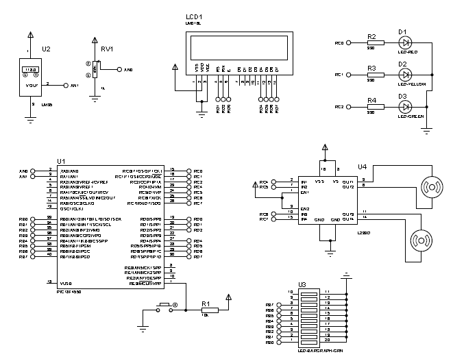
Schematic Diagram for 4x4 Keypad

//Keypad Driver: flex_kbd4x4.c
#define row0 PIN_B4 
#define row1 PIN_B5 
#define row2 PIN_B6 
#define row3 PIN_B7 
#define col0 PIN_B0 
#define col1 PIN_B1 
#define col2 PIN_B2 
#define col3 PIN_B3 

// Keypad layout: 
char const KEYS[4][4] = 
{{'7','8','9','/'}, 
 {'4','5','6','X'}, 
 {'1','2','3','-'}, 
 {'*','0','=','+'}}; 


#define KBD_DEBOUNCE_FACTOR 33 // Set this number to apx n/333 where 
// n is the number of times you expect 
// to call kbd_getc each second 

void kbd_init() 
//set_tris_b(0xF0); 
//output_b(0xF0); 
port_b_pullups(true);  

short int ALL_ROWS (void) 
if(input (row0) & input (row1) & input (row2) & input (row3)) 
   return (0); 
else 
   return (1); 


char kbd_getc() 
static byte kbd_call_count; 
static short int kbd_down; 
static char last_key; 
static byte col; 

byte kchar; 
byte row; 

kchar='\0'; 

if(++kbd_call_count>KBD_DEBOUNCE_FACTOR) 
  { 
   switch (col) 
     { 
      case 0: 
        output_low(col0); 
        output_high(col1); 
        output_high(col2); 
        output_high(col3); 
        break; 
    
      case 1: 
        output_high(col0); 
        output_low(col1); 
        output_high(col2); 
        output_high(col3); 
        break; 

      case 2: 
        output_high(col0); 
        output_high(col1); 
        output_low(col2); 
        output_high(col3); 
        break; 

      case 3: 
        output_high(col0); 
        output_high(col1); 
        output_high(col2); 
        output_low(col3); 
        break; 
      } 

   if(kbd_down) 
     { 
      if(!ALL_ROWS()) 
        { 
         kbd_down=false; 
         kchar=last_key; 
         last_key='\0'; 
        } 
     } 
   else 
     { 
      if(ALL_ROWS()) 
        { 
         if(!input (row0)) 
            row=0; 
         else if(!input (row1)) 
            row=1; 
         else if(!input (row2)) 
            row=2; 
         else if(!input (row3)) 
            row=3; 

         last_key =KEYS[row][col]; 
         kbd_down = true; 
        } 
      else 
        { 
         ++col; 
         if(col==4) 
            col=0; 
        } 
     } 
   kbd_call_count=0; 
  } 
return(kchar); 

//**********************************************************
//Main Program

#include <18F4550.h> // PIC18F4550 HEADER FILE
#fuses XT,NOWDT,NOLVP,NOPROTECT // EXTERNAL CLOCK, NO WATCH DOG TIMER, NO LOW VOLTAGE 
#device adc=10 // USE 10 BIT ADC QUANTIZATION
#use delay (clock=4M) // 4 MHZ CRYSTAL

#include <flex_lcd420.c>
#include <flex_kbd4x4.c>


//Main Program

void main()
{  
   char k;
   
   lcd_init();
   kbd_init();

   lcd_putc("\fReady...\n");
   //Pin Configuration
   
   while(true)
   {
      //Program start here
      k=kbd_getc();
      if(k!=0)
        if(k=='*')
         {
          lcd_putc('\f');
          delay_ms(100);
          lcd_putc("\fReady...\n");
         }
        else
          lcd_putc(k);
   }

}


Example of Keypad 4x3 Program

Result

Schematic Diagram


//Example of Program
#include <18F4550.h> // PIC18F4550 HEADER FILE
#fuses XT,NOWDT,NOLVP,NOPROTECT // EXTERNAL CLOCK, NO WATCH DOG TIMER, NO LOW VOLTAGE 
#device adc=10 // USE 10 BIT ADC QUANTIZATION
#use delay (clock=4M) // 4 MHZ CRYSTAL

#include <flex_lcd420.c>
#include <flex_kbd.c>


//Main Program

void main()
{  
   char k;
   
   lcd_init();
   kbd_init();

   lcd_putc("\fReady...\n");
   //Pin Configuration
   
   while(true)
   {
      //Program start here
      k=kbd_getc();
      if(k!=0)
        if(k=='*')
         {
          lcd_putc('\f');
          delay_ms(100);
          lcd_putc("\fReady...\n");
         }
        else
          lcd_putc(k);
   }

}

Saturday, April 19, 2014

Chapter 5 : Controlling DC Motor

Example of Circuit

//Exercise1Motor.c : Controlling Direction of MotorA and MotorB
#include <18f4550.h> // Header file
#fuses HS, NOWDT, NOPROTECT, NOLVP
#use delay (clock = 20M)
// Pin Definition
#define MOTORA_1     PIN_B0 //IN1
#define MOTORA_2     PIN_B1 //IN2
#define MOTORB_1     PIN_B2 //IN3
#define MOTORB_2     PIN_B3 //IN4
void main(){
     //Set PORTB as output
     set_tris_b(0x00);

     //Configure PWM Pinout
     setup_timer_2(T2_DIV_BY_4,254,1);//PWM OUTPUT CONFIGURATION
setup_ccp1(ccp_pwm); //PWM 1 DUTY CYCLE CONFIGURATION
setup_ccp2(ccp_pwm); //PWM 2 DUTY CYCLE CONFIGURATION
     while(true){
           //Turn On Motor A CW
           output_high(MOTORA_1);
           output_low(MOTORA_2);

           //Turn On Motor B CCW
           output_low(MOTORB_1);
           output_high(MOTORB_2);
     }
}


//*************************************************************

//Exercise2Motor.c : Controlling Speed of MotorA and MotorB
#include <18f4550.h7gt; // Header file
#fuses HS, NOWDT, NOPROTECT, NOLVP
#use delay (clock = 20M)
// Pin Definition
#define MOTORA_1     PIN_B0 //IN1
#define MOTORA_2     PIN_B1 //IN2
#define MOTORB_1     PIN_B2 //IN3
#define MOTORB_2     PIN_B3 //IN4
void main(){
     //Set PORTB as output
     set_tris_b(0x00);

     //Configure PWM Pinout
     setup_timer_2(T2_DIV_BY_4,254,1);//PWM OUTPUT CONFIGURATION
setup_ccp1(ccp_pwm); //PWM 1 DUTY CYCLE CONFIGURATION
setup_ccp2(ccp_pwm); //PWM 2 DUTY CYCLE CONFIGURATION
     while(true){
           //Turn On Motor A CW
           output_high(MOTORA_1);
           output_low(MOTORA_2);
           set_pwm1_duty(200); //Speed of MotorA

           //Turn On Motor B CCW
           output_low(MOTORB_1);
           output_high(MOTORB_2);
           set_pwm2_duty(150); //Speed of MotorB
     }
}


//*************************************************************

//Exercise3Motor.c : Controlling Motor using Buttons
#include <18f4550.h> // Header file
#fuses HS, NOWDT, NOPROTECT, NOLVP
#use delay (clock = 20M)
#include <lcd.c>
//Pin Definition for LCD
#define LCD_ENABLE_PIN     PIN_D0
#define LCD_RS_PIN         PIN_D1
#define LCD_RW_PIN         PIN_D2
#define LCD_DATA4          PIN_D4
#define LCD_DATA5          PIN_D5
#define LCD_DATA6          PIN_D6
#define LCD_DATA7          PIN_D7

//Pin Definition for Buttons
#define    BUTTON1    PIN_B4
#define    BUTTON2    PIN_B5

// Pin Definition For Motor
#define MOTORA_1     PIN_B0 //IN1
#define MOTORA_2     PIN_B1 //IN2
#define MOTORB_1     PIN_B2 //IN3
#define MOTORB_2     PIN_B3 //IN4
void main(){
     //Set PINB0-PINB3 as output PINB4-PINB7 as input
     set_tris_b(0xF0);

     lcd_init();

     //Configure PWM Pinout
     setup_timer_2(T2_DIV_BY_4,254,1);//PWM OUTPUT CONFIGURATION
setup_ccp1(ccp_pwm); //PWM 1 DUTY CYCLE CONFIGURATION
setup_ccp2(ccp_pwm); //PWM 2 DUTY CYCLE CONFIGURATION
     while(true){

           if(!input(BUTTON1)){
                //Turn On Motor A MotorB turn Off
                output_high(MOTORA_1);
                output_low(MOTORA_2);
                output_high(MOTORB_1);
                output_high(MOTORB_2);
                set_pwm1_duty(100); //Speed of MotorA
                printf(lcd_putc,”\fMOTORA Move\nMOTORB Stop”);
                delay_ms(100);
           }
           else if(!input(BUTTON2)){
                output_high(MOTORA_1);
                output_high(MOTORA_2);
                output_high(MOTORB_1);
                output_low(MOTORB_2);
                set_pwm2_duty(100);
                printf(lcd_putc,”\fMOTORA Stop\nMOTORB Move”);
                delay_ms(100);
           }
           else {
                output_high(MOTORA_1);
                output_high(MOTORA_2);
                output_high(MOTORB_1);
                output_high(MOTORB_2);
                printf(lcd_putc,”\fMOTORA Stop\nMOTORB Stop”);
                delay_ms(100);
           }
     }
}

//*************************************************************

//Exercise4Motor.c : Controlling Speed of Motor using Buttons
#include <18f4550.h> // Header file
#fuses HS, NOWDT, NOPROTECT, NOLVP
#use delay (clock = 20M)
#include <lcd.c>
//Pin Definition for LCD
#define LCD_ENABLE_PIN     PIN_D0
#define LCD_RS_PIN         PIN_D1
#define LCD_RW_PIN         PIN_D2
#define LCD_DATA4          PIN_D4
#define LCD_DATA5          PIN_D5
#define LCD_DATA6          PIN_D6
#define LCD_DATA7          PIN_D7

//Pin Definition for Buttons
#define    BUTTON1    PIN_B4
#define    BUTTON2    PIN_B5

// Pin Definition For Motor
#define MOTORA_1     PIN_B0 //IN1
#define MOTORA_2     PIN_B1 //IN2
#define MOTORB_1     PIN_B2 //IN3
#define MOTORB_2     PIN_B3 //IN4
void main(){
     int32 speed=50; //Speed of motor
     //Set PINB0-PINB3 as output PINB4-PINB7 as input
     set_tris_b(0xF0);

     lcd_init();

     //Configure PWM Pinout
     setup_timer_2(T2_DIV_BY_4,254,1);//PWM OUTPUT CONFIGURATION
setup_ccp1(ccp_pwm); //PWM 1 DUTY CYCLE CONFIGURATION
setup_ccp2(ccp_pwm); //PWM 2 DUTY CYCLE CONFIGURATION
     while(true){

           if(!input(BUTTON1)){
                speed++;
                output_high(MOTORA_1);
                output_low(MOTORA_2);
                output_high(MOTORB_1);
                output_low(MOTORB_2);
                set_pwm1_duty(speed); //Speed of MotorA
                set_pwm2_duty(speed);
                printf(lcd_putc,”\fSpeed = %ld”,speed);
                delay_ms(100);
           }
           else if(!input(BUTTON2)){
                speed--;
                output_high(MOTORA_1);
                output_low(MOTORA_2);
                output_high(MOTORB_1);
                output_low(MOTORB_2);
                set_pwm1_duty(speed); //Speed of MotorA
                set_pwm2_duty(speed);
                printf(lcd_putc,”\fSpeed = %ld”,speed);
                delay_ms(100);
           }
           if(speed>=200){
                speed=200;
           }
           else if(speed<=20){
                speed=20;
           }
     }
}


//*************************************************************
//Exercise5Motor.c : Controlling Speed of Motor using Potentiometer
#include <18f4550.h> // Header file
#fuses HS, NOWDT, NOPROTECT, NOLVP
#device ADC=10
#use delay (clock = 20M)
#include <lcd.c>
//Pin Definition for LCD
#define LCD_ENABLE_PIN     PIN_D0
#define LCD_RS_PIN         PIN_D1
#define LCD_RW_PIN         PIN_D2
#define LCD_DATA4          PIN_D4
#define LCD_DATA5          PIN_D5
#define LCD_DATA6          PIN_D6
#define LCD_DATA7          PIN_D7

//Pin Definition for Buttons
#define    BUTTON1    PIN_B4
#define    BUTTON2    PIN_B5

// Pin Definition For Motor
#define MOTORA_1     PIN_B0 //IN1
#define MOTORA_2     PIN_B1 //IN2
#define MOTORB_1     PIN_B2 //IN3
#define MOTORB_2     PIN_B3 //IN4
void main(){
     int32 speed=250; //Speed of motor
     int32 value;
     //Set PINB0-PINB3 as output PINB4-PINB7 as input
     set_tris_b(0xF0);
     lcd_init();

     //Configure Analog Input
     setup_adc_ports (ALL_ANALOG);
     setup_adc (ADC_CLOCK_INTERNAL);

     //Configure PWM Pinout
     setup_timer_2(T2_DIV_BY_4,254,1);//PWM OUTPUT CONFIGURATION
setup_ccp1(ccp_pwm); //PWM 1 DUTY CYCLE CONFIGURATION
setup_ccp2(ccp_pwm); //PWM 2 DUTY CYCLE CONFIGURATION
     while(true){

        set_adc_channel(2);
         value=read_adc();
         value=value*100/1023;
        
         if(value>=80)
         {           
            speed = speed+10;
            delay_ms(100);
         }
         else if (value<=30)   
         {
            speed = speed-10;
            delay_ms(100);
         }
        
         if (speed >= 100)
         {
            speed = 100;
         }
         else if(speed<=2)
         {
            speed=2;        
         }
        
         output_high(MOTORA_1);
         output_low(MOTORA_2);
         output_high(MOTORB_1);
         output_low(MOTORB_2);
         set_pwm1_duty(speed);
         set_pwm2_duty(speed);
         printf(lcd_putc,"\fSPEED %ld",speed);
         printf(lcd_putc,"\nPercentage=%d%%",(int)value);        
         delay_ms(10); 
   }
}


Sunday, March 30, 2014

Chapter 4 : ADC Programming

Example of Circuit
 
 
Exercise 1 :
 
//ExerciseADC1:Display Voltage Percentage and Temperature
#include <18f4550.h> //Header File
#fuses HS, NOWDT, NOLVP, NOPROTECT //Hardware Configuration
#device ADC=10 //Select 10 bit resolution
#use delay(clock=20M)
#include <lcd.c> //Driver for LCD
//Pin Definitions for LCD
#define   LCD_ENABLE_PIN   PIN_D0
#define   LCD_RS_PIN       PIN_D1
#define   LCD_RW_PIN       PIN_D2
#define   LCD_DATA4        PIN_D4
#define   LCD_DATA5        PIN_D5
#define   LCD_DATA6        PIN_D6
#define   LCD_DATA7        PIN_D7
//Main Function
void main(){
   //Variable declaration
   int32 value1, voltage, value2, temp, percent;
   //initialize LCD
   lcd_init();
   //ADC configuration
   setup_ADC(ADC_CLOCK_INTERNAL);
   setup_ADC_ports(ALL_ANALOG);
   while(true){
      //Program Start Here
      //Voltage
      set_adc_channel(0);
      value1=read_adc(); //Read analog signal
      voltage=value1*5/(1024-1); //Calculate conversion
      //Percentage
      percent=value1*100/(1024-1); //Calculate conversion
      //Temperature Sensor LM35
      set_adc_channel(1);
      value2=read_adc(); //Read analog signal
      temp=value2*5*100/1023; //Conversion
        
      //Display on LCD
      printf(lcd_putc,"\fVoltage = %dV",(int)voltage);
      printf(lcd_putc,"\nPercentage=%d%%",(int)percent);
      delay_ms(500);
      printf(lcd_putc,"\fSuhu=%.2f Degree",(float)temp);
      delay_ms(500);
   }
}
 
//**********************************************************
 
Exercise 2:
 
//ExerciseADC2: 3 LEDs will turn ON base on temperature
#include <18f4550.h>
#fuses HS,NOWDT,NOPROTECT,NOLVP
#device ADC=10
#use delay(clock=20M)
#include <lcd.c>
//Pin Definition
//Pin Definitions for LCD
#define   LCD_ENABLE_PIN   PIN_D0
#define   LCD_RS_PIN       PIN_D1
#define   LCD_RW_PIN       PIN_D2
#define   LCD_DATA4        PIN_D4
#define   LCD_DATA5        PIN_D5
#define   LCD_DATA6        PIN_D6
#define   LCD_DATA7        PIN_D7
 
//Pin Definition for LED
#define   RED      PIN_C0
#define   YELLOW   PIN_C1
#define   GREEN    PIN_C2

//Main Function
void main(){
   int32 value1, temperature;
  
   lcd_init();

   //Set PORT C as output
   set_tris_c(0x00);
   output_c(0x00); //Initialize PORT C
  
   //ADC configuration
      setup_ADC(ADC_CLOCK_INTERNAL);
      setup_ADC_ports(ALL_ANALOG);

   while(true){
      //Read Analog Signal
      set_adc_channel(1);
      value1=read_adc();
      temperature=value1*100*5/1023;
     
      if(temperature>=100){
  printf(lcd_putc,"\fSuhu Alert \n%.2f Celcius",(float)temperature);
         output_high(RED);
         output_low(YELLOW);
         output_low(GREEN);
         delay_ms(500);
      }
      else if(temperature<=95&&temperature>=25){
 printf(lcd_putc,"\fSuhu Normal \n%.2f Celcius",(float)temperature);
         output_low(RED);
         output_high(YELLOW);
         output_low(GREEN);
         delay_ms(500);  
      }
      else if(temperature<=20){
     printf(lcd_putc,"\fSuhu Low\n%.2f Celcius",(float)temperature);
         output_low(RED);
         output_low(YELLOW);
         output_high(GREEN);
         delay_ms(500);  
      }
   }
}


//**********************************************************

Exercise 3:

//ExerciseADC3 : Manipulating LCD for displaying ADC
#include <18f4550.h>
#fuses HS,NOWDT,NOPROTECT,NOLVP
#device ADC=10
#use delay(clock=20M)
#include <lcd.c>

//Pin Definition
//Pin Definitions for LCD
#define   LCD_ENABLE_PIN   PIN_D0
#define   LCD_RS_PIN       PIN_D1
#define   LCD_RW_PIN       PIN_D2
#define   LCD_DATA4        PIN_D4
#define   LCD_DATA5        PIN_D5
#define   LCD_DATA6        PIN_D6
#define   LCD_DATA7        PIN_D7

//Main Function
void main(){
   //Variable declaration
   int32 value1, voltage, value2, temp, percent;

   //initialize LCD
   lcd_init();

   //ADC configuration
   setup_ADC(ADC_CLOCK_INTERNAL);
   setup_ADC_ports(ALL_ANALOG);

   while(true){
      //Program Start Here

      //Voltage
      set_adc_channel(0);
      value1=read_adc(); //Read analog signal
      voltage=value1*5/(1024-1); //Calculate conversion

      //Percentage
      percent=value1*100/(1024-1); //Calculate conversion
      //Temperature Sensor LM35
      set_adc_channel(1);
      value2=read_adc(); //Read analog signal
      temp=value2*5*100/1023; //Conversion
        
      //Display on LCD
      printf(lcd_putc,"\fVoltage = %dV",(int)voltage);
      delay_ms(500);
      printf(lcd_putc,"\fSuhu=%.2f Degree",(float)temp);
      delay_ms(500);

   }
}


//**********************************************************
 
Exercise 4:
 

//ExerciseADC4: Controlling Motor via ADC
#include <18f4550.h>
#fuses HS,NOWDT,NOPROTECT,NOLVP
#device ADC=10
#use delay(clock=20M)
#include <lcd.c>


//Pin Definitions for LCD
#define   LCD_ENABLE_PIN   PIN_D0
#define   LCD_RS_PIN       PIN_D1
#define   LCD_RW_PIN       PIN_D2
#define   LCD_DATA4        PIN_D4
#define   LCD_DATA5        PIN_D5
#define   LCD_DATA6        PIN_D6
#define   LCD_DATA7        PIN_D7

//Pin Definition for LED
#define   Motor1_L      PIN_C4
#define   Motor1_R      PIN_C5
#define   Motor2_L      PIN_C6
#define   Motor2_R      PIN_C7


//Main Function
void main(){
   int32 value1, voltage;
  
   lcd_init();

   //Set PORT C as output
   set_tris_c(0x00);
   output_c(0x00); //Initialize PORT C
  
   //ADC configuration
      setup_ADC(ADC_CLOCK_INTERNAL);
      setup_ADC_ports(ALL_ANALOG);

   while(true){
      //Read Analog Signal
      set_adc_channel(0);
      value1=read_adc();
      voltage=value1*5/1023;
     
      if(voltage>=3){
         printf(lcd_putc,"\fVoltage \n%dV",(int)voltage);
         output_high(Motor1_L);
         output_low(Motor1_R);
         output_low(Motor2_L);
         output_low(Motor2_R);
         delay_ms(500);
      }
      else if(voltage<=2){
         printf(lcd_putc,"\fVoltage \n%dV",(int)voltage);
         output_low(Motor1_L);
         output_low(Motor1_R);
         output_high(Motor2_L);
         output_low(Motor2_R);
         delay_ms(500);  
      }
      else{
         printf(lcd_putc,"\fVoltage \n%dV",(int)voltage);
         output_low(Motor1_L);
         output_low(Motor1_R);
         output_low(Motor2_L);
         output_low(Motor2_R);
         delay_ms(500);  
      }
   }
}


//**********************************************************
 
Exercise 5:

//ExerciseADC5: Controlling LED bargraph
#include <18f4550.h>
#fuses HS,NOWDT,NOPROTECT,NOLVP
#device ADC=10
#use delay(clock=20M)
#include <lcd.c>

//Pin Definition
//Pin Definitions for LCD
#define   LCD_ENABLE_PIN   PIN_D0
#define   LCD_RS_PIN       PIN_D1
#define   LCD_RW_PIN       PIN_D2
#define   LCD_DATA4        PIN_D4
#define   LCD_DATA5        PIN_D5
#define   LCD_DATA6        PIN_D6
#define   LCD_DATA7        PIN_D7


//Main Function
void main(){
   int32 value1, voltage;
  
   lcd_init();


   //Set PORT B as output
   set_tris_b(0x00);
   output_b(0x00); //Initialize PORT C
  
   //ADC configuration
      setup_ADC(ADC_CLOCK_INTERNAL);
      setup_ADC_ports(ALL_ANALOG);

   while(true){
      //Read Analog Signal
      set_adc_channel(0);
      value1=read_adc();
      voltage=value1*5/1023;
   
   if(voltage==0){
         printf(lcd_putc,"\fVoltage \n%dV",(int)voltage);
         output_b(0);
         delay_ms(500);
      }
      else if(voltage==1){
         printf(lcd_putc,"\fVoltage \n%dV",(int)voltage);
         output_b(3);
         delay_ms(500);  
      }
      else if(voltage==2){
         printf(lcd_putc,"\fVoltage \n%dV",(int)voltage);
         output_b(15);
         delay_ms(500);  
      }
   else if(voltage==3){
         printf(lcd_putc,"\fVoltage \n%dV",(int)voltage);
         output_b(31);
         delay_ms(500);  
      }
   else if(voltage==4){
         printf(lcd_putc,"\fVoltage \n%dV",(int)voltage);
         output_b(63);
         delay_ms(500);  
      }
   else if(voltage==5){
         printf(lcd_putc,"\fVoltage \n%dV",(int)voltage);
         output_b(255);
         delay_ms(500);  
      }
   }
}


Thursday, March 13, 2014

Chapter 3 : LCD Programming

LCD Circuit

//Exercise1LCD : Display “WELCOME”
#include <18f4550.h> //Header File
#fuses HS, NOWDT, NOLVP ,NOPROTECT
#use delay (clock=20M)
//Define LCD PIN
#define LCD_ENABLE_PIN  PIN_D0
#define LCD_RS_PIN      PIN_D1
#define LCD_RW_PIN      PIN_D2
#define LCD_DATA4       PIN_D4
#define LCD_DATA5       PIN_D5
#define LCD_DATA6       PIN_D6
#define LCD_DATA7       PIN_D7
 
//Include LCD Library
#include //Library LCD
 
//Main Function
Void main()
{
   lcd_init(); //Initialize LCD
  
   While(true)
   {
         Printf(lcd_putc,”\fWELCOME\nMY FRIEND”);
 
 
                      delay_ms(100);
 
     }
 
}
 
/**************************************************************/
 
 
//Exercise2LCD : Display “WELCOME” at correct coordinate
 
#include <18f4550.h>//Header File
#fuses HS, NOWDT, NOLVP ,NOPROTECT
#use delay (clock=20M)
 
//Define LCD PIN
#define LCD_ENABLE_PIN  PIN_D0
#define LCD_RS_PIN      PIN_D1
#define LCD_RW_PIN      PIN_D2
#define LCD_DATA4       PIN_D4
#define LCD_DATA5       PIN_D5
#define LCD_DATA6       PIN_D6
#define LCD_DATA7       PIN_D7
 
//Include LCD Library
#include //Library LCD
 
//Main Function
 
Void main()
{
     Lcd_init(); //Initialize LCD
    
     While(true)
     {
          Lcd_putc(“\f”); //Clear screen
          Lcd_gotoxy(3,1);
          Lcd_putc(“PRAY TO”);
          Lcd_gotoxy(5,2);
          Lcd_putc(“MH370”);
          Delay_ms(100);
 
 
     }
 
}
 
/**************************************************************/
 
//Exercise3LCD : Message blink
 
#include <18f4550.h>//Header File
#fuses HS, NOWDT, NOLVP ,NOPROTECT
#use delay (clock=20M)
 
//Define LCD PIN
#define LCD_ENABLE_PIN  PIN_D0
#define LCD_RS_PIN      PIN_D1
#define LCD_RW_PIN      PIN_D2
#define LCD_DATA4       PIN_D4
#define LCD_DATA5       PIN_D5
#define LCD_DATA6       PIN_D6
#define LCD_DATA7       PIN_D7
 
//Include LCD Library
#include //Library LCD
 
//Main Function
 
Void main()
{
     Int I;
     Lcd_init(); //Initialize LCD
    
     While(true)
     {
          For(i=0; i<=4; i++)
          {
             
              Lcd_putc(“\f”); //Clear screen
              Delay_ms(250);
              Lcd_gotoxy(3,1);
              Lcd_putc(“PRAY TO”);
              Lcd_gotoxy(5,2);
              Lcd_putc(“MH370”);
              Delay_ms(250);
          }
 
 
     }
 
}
 
/**************************************************************/
 
//Exercise4LCD : Scroll Message Left Right
 
#include <18f4550.h>//Header File
#fuses HS, NOWDT, NOLVP ,NOPROTECT
#use delay (clock=20M)
 
//Define LCD PIN
#define LCD_ENABLE_PIN  PIN_D0
#define LCD_RS_PIN      PIN_D1
#define LCD_RW_PIN      PIN_D2
#define LCD_DATA4       PIN_D4
#define LCD_DATA5       PIN_D5
#define LCD_DATA6       PIN_D6
#define LCD_DATA7       PIN_D7
 
//Include LCD Library
#include //Library LCD
 
//Main Function
 
Void main()
{
     Int I;
     Lcd_init(); //Initialize LCD
    
     While(true)
     {
          For(i=1; i<=2; i++)
          {
             
              Lcd_putc(“\f”); //Clear screen
              Lcd_gotoxy(i,1);
              Lcd_putc(“PRAY TO”);
              Lcd_gotoxy(16-i,2);
              Lcd_putc(“MH370”);
              Delay_ms(250);
          }
 
 
     }
 
}
 
/**************************************************************/
//Exercise5LCD : Scroll Message Up Down
 
#include <18f4550.h>//Header File
#fuses HS, NOWDT, NOLVP ,NOPROTECT
#use delay (clock=20M)
 
//Define LCD PIN
#define LCD_ENABLE_PIN  PIN_D0
#define LCD_RS_PIN      PIN_D1
#define LCD_RW_PIN      PIN_D2
#define LCD_DATA4       PIN_D4
#define LCD_DATA5       PIN_D5
#define LCD_DATA6       PIN_D6
#define LCD_DATA7       PIN_D7
 
//Include LCD Library
#include //Library LCD
 
//Main Function
 
Void main()
{
     Int I;
     Lcd_init(); //Initialize LCD
    
     While(true)
     {
          For(i=1; i<=2; i++)
          {
             
              Lcd_putc(“\f”); //Clear screen
              Lcd_gotoxy(5,i);
              Lcd_putc(“PRAY TO”);
              Lcd_gotoxy(5,i-1);
              Lcd_putc(“MH370”);
              Delay_ms(250);
          }
 
 
     }
 
}
 
/**************************************************************/
 
//Exercise4LCD : Button
 
#include <18f4550.h>//Header File
#fuses HS, NOWDT, NOLVP ,NOPROTECT
#use delay (clock=20M)
 
//Define LCD PIN
#define LCD_ENABLE_PIN  PIN_D0
#define LCD_RS_PIN      PIN_D1
#define LCD_RW_PIN      PIN_D2
#define LCD_DATA4       PIN_D4
#define LCD_DATA5       PIN_D5
#define LCD_DATA6       PIN_D6
#define LCD_DATA7       PIN_D7
#define BUTTON          PIN_B0
//Include LCD Library
#include //Library LCD
//Main Function 
Void main()
{
     Set_tris_b(0xff);
     Int I;
     Lcd_init(); //Initialize LCD 
     While(true)
     {
          If(input(BUTTON))
          {
              Lcd_putc(“\fNO BUTTON\nPRESSED”);
              Delay_ms(100);
          }
          Else
          {
               For(i=1; i<=16; i++)
               {
                   Lcd_putc(“\f”); //Clear screen
                   Lcd_gotoxy(i,1);
                   Lcd_putc(“PRAY TO”);
                   Lcd_gotoxy(16-i,2);
                   Lcd_putc(“MH370”);
                   Delay_ms(250);
              }
          }
          }
     }
} 
/**************************************************************/