The ladder diagram has and continues to be the traditional way of representing electrical sequences of operations. These diagrams represent the interconnection of field devices in such a way that the activation, or turning ON, of one device will turn ON another device according to a predetermined sequence of events.

The original ladder diagrams were established to represent hardwired logic circuits used to control machines or equipment. Due to wide industry use, they became a standard way of communicating control information from the designers to the users of equipment. As programmable controllers were introduced, this type of circuit representation was also desirable because it was easy to use and interpret and was widely accepted in industry.
Programmable controllers can implement all of the “old” ladder diagram conditions and much more. Their purpose is to perform these control operations in a more reliable manner at a lower cost. A PLC implements, in its CPU, all of the old hardwired interconnections using its software instructions. This is accomplished using familiar ladder diagrams in a manner that is transparent to the engineer or programmer.
Contacts Symbols in PLCs
Programmable controller contacts and electro mechanical relay contacts operate in a very similar fashion. For example , let us take relay which has two sets of contacts, one normally open contact and one normally closed contact. If relay coil A is not energized (i.e it is OFF), contact A-1 will remain open and and contact A-2 will remain closed. Conversely if coil A is energized or turned ON, contact A-1 will close and contact A-2 will open.


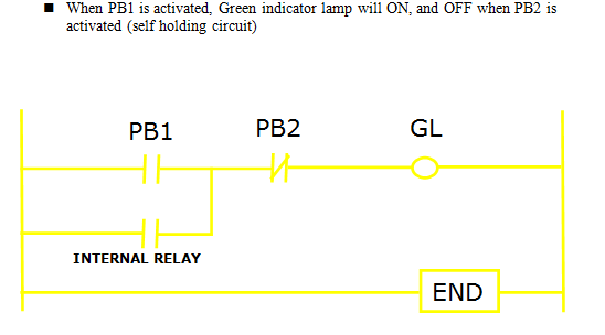
Example 1 :

Example 2 :
2 comments:
industrial automation
Study about PLC Programming Tutorials and Ladder Logic at Instrumentation Tools and post your queries at PLC Forum
Post a Comment